FOCUS ON FAST RESULTS
Create templates from sanitary layouts, making it convenient to reuse them in similar rooms via the Side Browser.
Sanitary objects, including sets, decorations, murals, niches, doors, shower doors, and shower drain systems, can be saved. Access templates easily in the Side Browser under the “Layout Templates” tab.
To save the sanitary template:
Create the sanitary layout.
Open the “Layout Templates” tab in the Side Browser.
Click the “Create” button to generate a template from the current project.
Enter a name for your template and click OK.
With the Kitchen functionality in ViSoft Premium, you can quickly and easily plan kitchens:
Access the ViSoft Kitchen Basic database
Use the Kitchen Designer module for fast creation of kitchens in various shapes
Select and modify program variations
Save and apply kitchen templates
Replace kitchen cabinets with the required size and type swiftly
Block calculation with manufacturer discounts directly during planning and variant changes
These features in ViSoft Premium enable to creation and showcasing of kitchen designs efficiently, minimizing time and effort while maximizing results.
Shower drain systems can be installed on the floor and on murals in ViSoft.
This function allows showers to be designed innovatively by entering the size, type, and slope in %, and selecting different types of drains and different drain positions. Size changes can be made easily with a double-click or by directly entering the width and length in the shower drain wizard.
To use this option, drag and drop the shower drain system onto the floor or wall in 2D or 3D mode. If the wall is moved, resized, or deleted, the shower drain system will adjust accordingly. The maximum height of the wall is 50 cm.
To change the size of an object, open the Properties panel and select the Size Variation tab.
The available parameters vary by object; some have one adjustable parameter, while others offer two or more.
There are very large tiles that can be laid across several walls or masonry. It is difficult to manually set the starting point for a continuous image. “Create image processing” generates an uninterrupted pattern. To do this, tile connected walls and masonry with the same large tile. The starting points of the individual areas are irrelevant. It is best to tile the first area using drag & drop from the tile side browser. Then copy this area by right-clicking and selecting “Copy tiling” and then right-clicking and selecting “Paste” several times while holding down the Ctrl key.
To use this feature:
Tile connected walls and murals with one image
Right-click on the wall or mural
Select “Create continuous image”
This update introduces several improvements to the countertop mural functionality. The key changes focus on enhancing the mounting height calculations, modifying the default mounting height, updating the icon for the countertop mural, and adding new options in the room’s mural tab.
Updates:
Improved calculation of mounting height and tiled countertop height
Updated icon for countertop mural
Change in Default Mounting Height
Addition of Pipe Shaft and Countertop to the “Room > Mural” Tab
The “Optimize Worktop” function visually optimizes the layout of a large tile by simulating a continuous design across cuts.
When clicking the Optimize Worktop button:
A window opens with layout options.
Select Continuous Veining to maintain the natural flow of the pattern across cut pieces. Use the Zoom in/out button for adjustments.
Zoom in/out buttons: Adjust the view scale in the new window for better control and visibility while working on your layout.
Export in CAD: Use the Export in CAD button to export your tile layout directly to a DXF file, compatible with most CAD software. This enables precise editing or integration into other design workflows.
Click Apply. The tile automatically arranges so that each cut aligns visually, creating a seamless effect.
Tile reuse displays the cut layout. These sheets enable to review and work with the optimized design.
This feature is useful when working with materials that have veins or patterns, ensuring a more aesthetically pleasing result.
This capability provides various creative design options for customized tile layouts. Create plinths, linear patterns, borders, or accent strips.
How does it work? Create a region, choose its thickness, and place any tile you like.
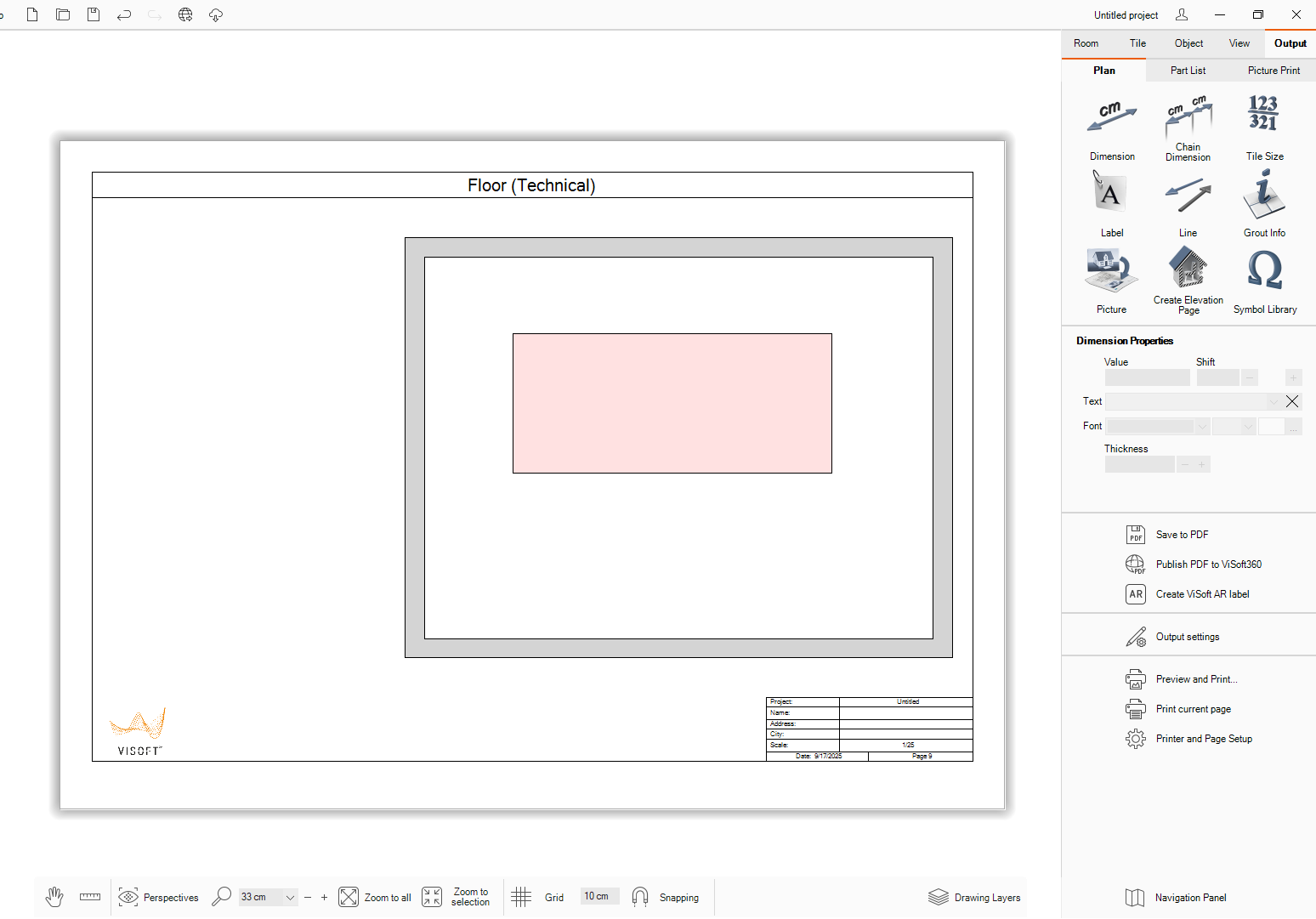
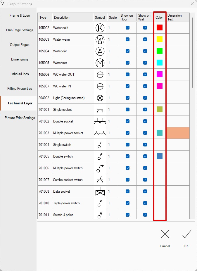
Then open the Output menu, go to the Part List section, and click on the icon
In the tile offcuts window, change the way of tile reuse to Free-Tile texture.
Now the tile you have placed will be calculated as one piece cut into stripes.
Tiles (or partial tiles) that are intentionally placed at the center or focal point of a surface. These may include cut tiles used as decorative elements such as medallions, borders, or inlays. The layout is designed so that the tiles do not connect to walls, edges, or factory borders, emphasizing their standalone decorative function.
Steps to use this feature:
Create region with thickness(height) from 5-25 or more
Tile surface (wall)
Tile region
Output>Part List>Tile
In the tile part list window column reused tile click on the icon
In the tile offcuts window, you can see how the tile will be cut. There are 7 “Ways of tile reuse” to choose from.
Also, you can change the kerning width and the background behind the tile
Database: Schedel Bad & Design GmbH + Schlüter
These items can be tiled directly. Internally the object is converted into a tileable mural.
How to Use:
Quick Room
3D View
Place object from Database: Schedel Bad & Design GmbH (Material type: Object tileable)
4.1 Place the tile on the object (all parts from tileable material convert into a placed tile)
This page provides detailed technical specifications and design data for the Floor view in a project. To provide engineers and architects with an at a glance view of the structural, architectural, or utility details.
This page auto-creates when there is one or more installation (sanitary, electrical, heating, ventilation) items in the project.
Symbols can be added by drag & drop them from the symbol library in the side browser. These are automatically added to the legend.
Symbol can be added from the side browser Symbol library by drag&drop
Added a new hatch drawing type that enables the creation of complex wall hatch styles, including single-stud and double-layered wall designs. This feature improves wall layer visualization in drawings.
Steps to Apply the New Hatch Style:
Open Wall or Mural Properties
Click on Hatch Style Image
Select Desired Hatch Style
Visual Confirmation in Output
Ensure Output Visibility
Open Output Settings: To ensure the hatch is visible in your final output, go to the Filling Properties tab.
Specify Filling Type: In the Output Settings, specify the filling type of walls and murals on the plan as “Hatch”. This is crucial, as hatches will only be visible in the final output when this setting is applied.
A new button labeled “Apply Drawing Options to All” has been added to the Mural Properties panel. This button allows users to apply the current mural’s basic drawing options to all other murals within the same project, with the following exceptions:
Exclusions:
Shower Drain Murals: Drawing options are not applied to murals designated as shower drains.
Advanced Properties: Only basic drawing options are applied. Advanced mural properties are excluded from this action.
The output settings include a “Color” column, allowing you to assign individual colors to each symbol. The description can be edited to customers requirements.
Configure a unique color for every symbol, enabling clearer visual distinction and improved readability in the project’s output.
To use this feature, simply set the desired color in the “Color” column for each symbol during configuration.
This feature allows the creation of custom folders and subfolders within a symbol library in ViSoft Premium in the Output tab. It helps organize the symbols in a structured hierarchy, allowing users to easily manage and access them in the library. Creation of subfolders is possible only in custom folders
Allowing Users to View and Edit Folders via ViSoft Premium Interface or the File Explorer (default C:\ProgramData\ViSoft\ViSoftPremium\PublicUserData\Output)
Steps to create a folder in the symbol library:
Open the Output tub
Open symbol library window
Press the new folder in the left corner
Click on custom folder and create a new folder
Subfolders and custom folders can be used via left Side browser
A new feature, “Create..”, has been introduced to enhance the symbol library management. This feature allows users to add new symbols only to custom folders and supports symbols in the .emf (Enhanced Metafile) format. For optimal display, the image size of the symbol should be a maximum of 250×250 pixels. Only .emf files are supported at this time. Other formats will not be accepted. Symbols can be copied in the standard library using the context menu copy/paste
Open the Symbol Library
Access the symbol library from the Visoft Premium.
Choose or Create a Custom Folder
Navigate to an existing custom folder or create a new one where the symbol will be added.
Open the Context Menu or Use the Create Button
Right-click inside the folder to open the context menu, then click “Create”,
OR
Click the “Create” button located in the bottom-right corner of the interface.
Add the Symbol
The folder will open in the symbol creation view.
Choose the symbol file in .emf format from your file system.
Preview and Confirm
The symbol will be displayed exactly as it appears in the .emf file.
The User Interface (UI) is optimized for Full HD resolution (1920 × 1080). This ensures that all interface components can be seen with the navigation toolbar open. Without scrolling and provide a consistent user experience across all pages. This helps beginners to find functions easy.
Pipe Shaft and Countertop murals in Room > Mural tab.
Scrollbars throughout the application enhance consistency, usability, and visual integration with the overall UI.
Fill the floor and mural niches with water to create realistic pools in ViSoft Premium.
Steps to fill a niche with water:
Create a free niche in the floor or mural.
Navigate to Object → Sanitary.
Click on Fill with Water.
Hover over the niche and click at the desired location to set the water level.
Adjusting or removing water in a niche:
Repeat the steps to fill the niche with a different water level. The previous water will be removed and replaced automatically.
When editing the niche, the water shape will adjust to fit the updated form.
To completely remove water from the niche, use the “Release Water” function in the context menu.
The tiled niches are easy to fill with water.
This process can occur in 2D or 3D.
In 2D, the water automatically fills to a level 5 cm below the top edge.
In 3D, users can select the water level by clicking on the desired height on the niche side.
Users can also remove the water using the “Delete” button, just like with a simple object.
Include a disk space counter to display the storage used by rendering tasks in real-time. This feature allows users to monitor disk usage effectively.
Export format: IFC 2×3 in ViSoft Premium
ViSoft Premium allows exporting to the IFC 2×3 format.
To export, follow these steps:
Go to File > Export > Export 3D.
Select IFC.
In the new window, choose IFC 2×3 from the dropdown list.
Also enable or disable specific objects such as windows, doors, and other elements before exporting, giving you full control over the contents of the IFC file.
GAEB Export Option in ViSoft Premium
ViSoft Premium includes an option to export a GAEB file directly within the main project archive. With the checkbox, users can easily include the GAEB (X83) file as part of the full project export for more convenient data handling. Without checking the GAEB files have to be exported separately with
File> Export> Export to GAEB XML
Enable this feature via File> Preferences> Advanced.
“Shortcuts” button is available in the Help menu. It opens the FAQ Web page
(Keyboard Shortcuts 2025 – ViSoft Help Center) in the default browser.
Contains Keyboard Shortcuts for Visoft Premium and add-ons(e.g., Visoft Viewer, Tile Browser).
Objects can snap to components inside groups. For example, a bath mixer can be snapped to a washbasin even when the basin is part of a group. When the group is moved, the snapped object remains anchored to its snapping point.
Numeric input fields support inline (simple) arithmetic expressions. This means you can enter simple math operations directly into the field, and the system will automatically calculate the result.
Expressions example: 377+25
Once entered, the field will evaluate the expression and display the result
This option allows to lock the camera’s tilt (rotation around the viewing axis) when navigating a 3D project. When enabled, the camera will maintain a level horizon by preventing any roll or tilt movement. This is especially useful for any scenario where a stable and upright view is important. Falling lines will be avoided.
How to use:
Open project
Open View>Camera tab
Click on the lock tilt
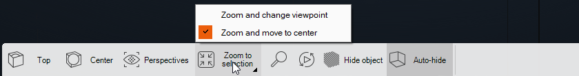
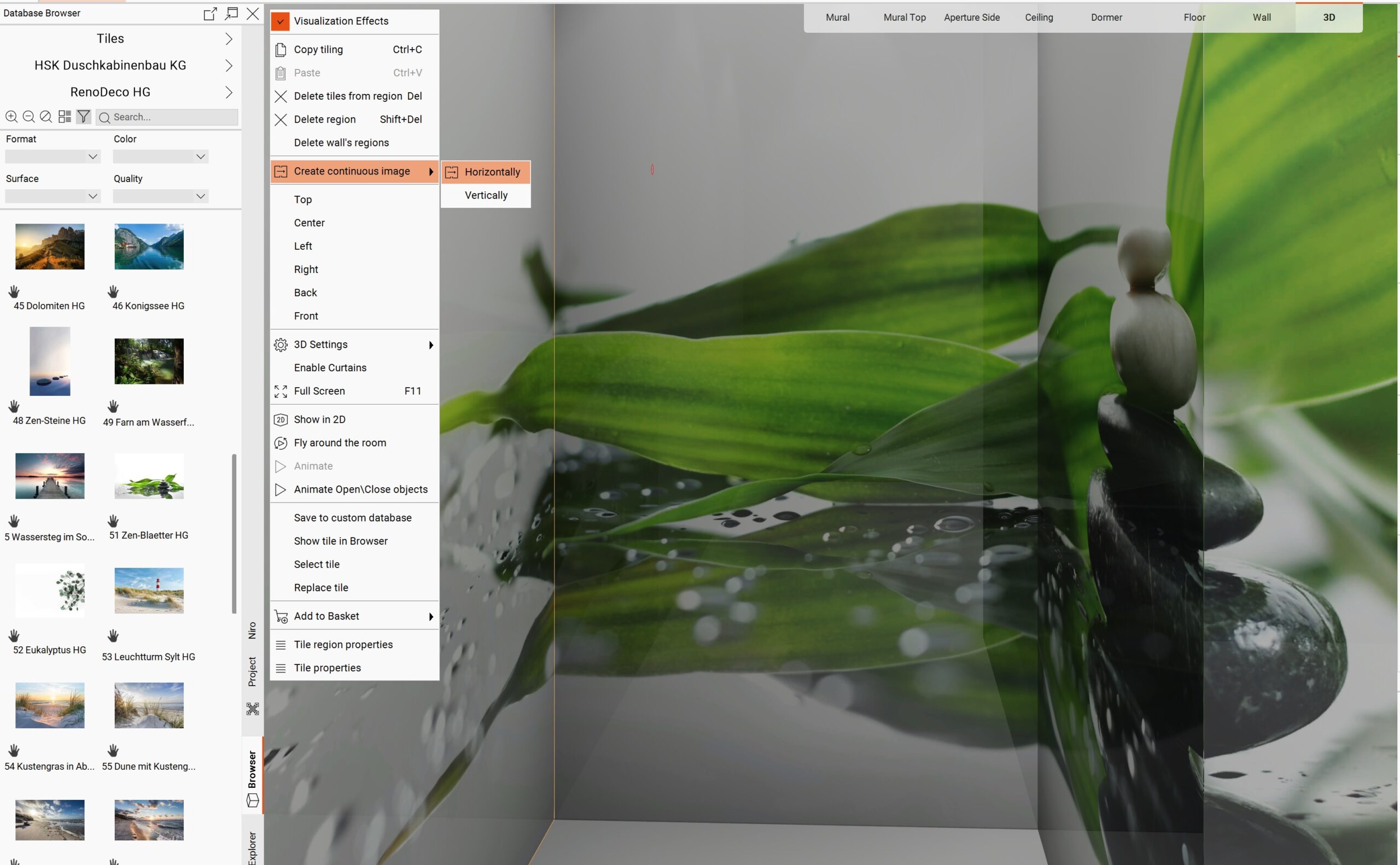
A new Camera Zoom to Region and Zoom & Move to Center functionality has been added to enhance navigation in the 3D View. These tools allow users to quickly focus on specific areas or objects in the scene, streamlining inspection, modeling, and interaction workflows.
To use the new zoom features:
Open the 3D View.
Click the Zoom button( ) located in the bottom menu.
Choose a region in the 3D view by clicking and dragging a selection box.
After selecting an object, two camera positioning options are available:
The camera zooms into the selected object.
The viewpoint remains the same — the camera only changes its distance to the target.
The selected object is centered in the viewport.
The camera repositions itself to ensure the selected area is both zoomed in and centered in the view.
The technical region supports in 2D both electrical heating mats and plumbing installations, applicable to floors, murals, ceilings, and walls. This feature enhances design accuracy, system coordination, and visual clarity in technical drawings across all project types. Supports both floor and wall placements for heating and plumbing regions. Ideal for underfloor heating, wall-mounted heating systems, wet area plumbing, and embedded piping layouts.
How to use:
Create room
Tile>Region
Create any region in 2D or 3D
Open region context menu
Convert to technical> choose plumbing or electrical
Placement of a technical region automatically creates a corresponding technical floor or wall page. The exception is the ceiling sheet, which has no technical page.
Electrical heating mats and plumbing installations are included in the part list under the Material Sheet in the output report. These components are measured and calculated in square meters (sqm).
Touch Support in ViSoft | ViPlan : User Guide
Overview
ViSoft | ViPlan fully supports touch interactions, allowing users to design bathrooms using touch gestures. This enhancement allows accessibility and usability on touchscreen devices such as tablets and interactive displays.
Supported Touch Gestures
The following gestures are now available for seamless interaction with the interface:
Tap: Equivalent to a mouse click, used for selecting objects, buttons, and UI elements.
Swipe: Allows for panning across the workspace or navigating through menus.
Pinch-to-Zoom: Enables zooming in and out using two fingers for a more detailed view of the bathroom layout.
Long Press: Used to activate an object before it can be moved (a loading bar fills up to indicate readiness).
Drag & Drop: Used after a long press to move and position objects within the design workspace.
Key Functionalities
Adding Elements: Users can tap on a component (e.g., bathtub, sink, or tiles) and drag it into the workspace.
Resizing & Rotating: Pinch to zoom or drag corners of selected objects to adjust their size.
Moving Objects: Long press an item to activate it (indicated by a loading bar), then drag it to a new location.
Navigation Modes: Users can switch between different viewing modes – Floor, Wall, and 3D – for better visualization and editing.
Best Practices for Touch Interaction
Use a stylus for precise object placement when working on smaller screens.
Ensure touch gestures are performed smoothly to avoid accidental actions.
Conclusion
The integration of touch support in ViSoft | ViPlan enhances the design experience, making it more intuitive and accessible for touchscreen users. Future updates may include additional refinements based on user feedback.
For any issues or suggestions, please contact our support team.
The Free Move toggle allows users to freely reposition objects in the 3D view without snapping to a predefined grid or alignment rules. This feature is useful for quick layout experiments, detailed object placement, and fine-tuning.
How It Works:
A toggle button labeled “Free Move” is available in the 3D toolbar.
When enabled, users can drag and move objects in any direction without restrictions.
When disabled, objects snap to the grid or existing constraints, as before.
This setting affects only the current 3D session and does not influence 2D layout behavior.
Use Cases:
Adjusting decorative items (e.g., plants, furniture) with precision.
Creating asymmetrical or irregular layouts.
Previewing alternative placements before committing to precise positioning.
The “Favorites” feature in ViPlan allows users to quickly add tiles and sanitary items to a list of frequently used elements, streamlining the design process.
How It Works:
Add to Favorites: Click the star icon next to a tile or sanitary item to add it to your favorites.
View Favorites: Access all favorite items in the “My Favorites” section in the toolbar.
Remove from Favorites: Click the star icon again or use the context menu to remove an item.
The star icon next to each item indicates whether it’s in the favorites list.
The “My Favorites” section allows quick access to saved items.
This feature enhances efficiency by providing easy access to frequently used items, saving time during the design process.
Sanitary objects like toilets and bidets automatically snap and rotate to fit corner murals in 3D view.
Available in: 3D view
Applies to: Sanitary objects + corner murals
The Niches feature is available in the Doors & Windows section. Users can now insert recessed wall spaces (niches) into their designs to enhance both functional and aesthetic aspects of a room. Niches are available in both 2D and 3D modes.
A category called Niches is available within the Doors & Windows catalog.Niches can be placed directly onto walls in:
2D mode — for precise wall positioning using a top down view.
3D mode — for intuitive visual placement and realistic previews.
Niches do not get tiled automatically upon placement. However:
If you place the niche first and then apply tiles using the “Apply to all walls” button, the niche will be tiled together with the wall.
Each niche can be adjusted for:
Width
Height
Depth
Position (horizontal and vertical)
The niche automatically cuts into the wall when placed
Niches can be added to:
Murals
Blocks
Notes
Niches are static elements – they do not contain shelves or lighting by default.
Niches can be added to:
Murals
Blocks
Currently available only on vertical walls (not sloped surfaces).
This feature allows registered users to download 3D projects from our Visoft360 website.
Go to the Explore section.
Filter projects by 3D Models.
Select the desired project.
Click the Download button under the project.
Security encoding is available for all items uploaded to 360, including projects, media, and assets. This makes it impossible to guess item IDs. The protection is applied automatically during export, ensuring that everything shared externally is secure by default.
Enable animation – Enables or disables animations for the 3D object if it has any predefined movements.
Show rotation button – Displays or hides a button that triggers automatic object rotation.
Enable shadow ground – Adds a soft shadow beneath the object to create a more realistic appearance.
Animate scene after load – Controls the initial animation where the project scales up as if flying toward the user. Disabling stops this animation.
Environment map – Changes the lighting and reflections around the object by applying a specific environment:
Grayscale forest – A neutral, soft grayscale forest background that provides natural lighting and subtle reflections.
Bathroom – A bright, indoor environment with reflective surfaces, simulating a typical bathroom setting.
Background – Defines the background color behind the 3D object:
Primary – Uses the main theme color of the application.
Secondary – Applies an alternative theme color for variation.
White – Sets a clean, neutral white background for a minimalistic look.
These settings give users greater flexibility in adjusting the appearance and environment of 3D objects within ViSoft360.
This viewer allows users to interact with 3D furniture models directly in the browser https://viewer3d.visoft.de/
Choose from a variety of furniture models
Models are grouped by category for easy browsing
Change the colors and materials of components
Toggle between available variations
Updates are reflected instantly in the 3D view
Rotate and zoom the model freely
Reset the camera to the default angle
Enable/disable object animation (e.g., object flies in)
Change background color or texture
Apply HDR lighting effects
Hide/show customization panel
Copy the direct link to the current configuration
Generate iframe embed code with adjustable size
The embedded version has limited functionality
Search and browse available models
Organized by categories
Displays the selected object
Contains control buttons:
Reset camera angle
Share (link + embed code)
HDR toggle
Background switch
Object animation toggle
Hide/show right panel
Color and material options
Dropdowns for variation selection (e.g., handle type)
Updates the model in real time
You have the opportunity to test ViSoft Premium 2026 for 14 days free of charge and with no obligation to the full functionality.
Mercedesstraße 19
71063 Sindelfingen, Germany
Tech.support: +49 7031 / 49165-99
© 2026 ViSoft GmbH