

Complete guide to application default settings and data locations
The System Preferences window stores application-wide choices for ViSoft Premium. It covers language, project storage, drawing defaults, tiling behavior, 2D and 3D display, rendering, camera behavior, updates, the Side Browser, print and output configuration, and advanced data locations. Open it with File > Preferences or Ctrl+K.
Opening System Preferences
UI path: File > Preferences or Ctrl+K
The window opens with thirteen sections in the left navigation. Changes are accepted with OK or discarded with Cancel. The bottom bar also provides Import, Export, Reset to defaults, and Compare settings….
- Import – loads a saved preference configuration for review and use.
- Export – saves the current preference configuration so it can be backed up or reused or delivery to other computer.
- Reset to defaults – returns preference values to the application’s defaults. Export first when the current configuration may be needed again.
- Compare settings… – opens the comparison workflow for preference configurations.
- Cancel – closes the window without accepting the pending edits.
- OK – accepts the current preference values and closes the window.
Figure 1: Open File > Preferences or press Ctrl+K

General
UI path: File > Preferences > General
General sets the regional format, default project storage, Auto-Recovery policy, and how project-related images are stored.
Regional Settings
- Language – selects the ViSoft Premium interface language.
- Currency – sets the currency used where ViSoft displays or calculates monetary values.(This paramter is set by Windows region settings)
- Measurement System – sets the unit system, such as Metric (cm).
Project Settings
- Projects location – sets the default folder used for project storage.
- Save Auto Recovery project every – enables periodic Auto-Recovery and sets the interval in minutes.
- Limit number of Auto-Recovery files – keeps only the configured number of recovery files.
- Delete Auto-Recovery files older than – uses an age limit instead of a file-count limit when selected.
- Save texture images to project folder – copies or keeps texture images with the project folder for project portability.
- Use custom folder to save pictures – routes saved pictures to a user-selected folder when enabled.
Figure 2 General

Interface
UI path File > Preferences > Interface
Interface controls visual appearance, startup and notification behavior, tooltips, full-screen taskbar visibility, and the buttons shown in the main ViSoft menu.
Appearance
- Color Theme – selects the application theme, such as Light.
- Selection Color – sets the highlight color used for selected interface or planning elements.
Options
- Show Welcome Screen at startup – opens the Welcome Screen when ViSoft Premium starts.
- Notify me about incoming messages from ViSoft Message Center – shows notifications for new Message Center items.
- Show help tooltips – shows explanatory tooltips for supported controls.
- Show Windows taskbar in full-screen mode – keeps the Windows taskbar visible while ViSoft uses full-screen mode.
Select main menu buttons
Check a command to show its button in the main menu. Use the up and down arrows to change the order. Select All and Select None apply a bulk selection. The list can include project commands, Undo and Redo, ViSoft 360 Online Service, ViSoft Message Center, Updates Manager, ViSoft AI Assistant, Project variations, ViMotion, picture and panorama saving, Photo Tuning, and Price.
Figure 3 Interface

Defaults
UI path File > Preferences > Defaults
Defaults defines the starting geometry, materials, and drawing representation used when new planning elements are created. It contains the Walls, Murals, Doors / Windows, and Sanitary tabs.
Walls
- Walls Default size – sets Height and Thickness for newly created walls.
- Surface material – selects the initial wall surface material.
- Building material template – selects the construction material template used for the wall.
- Line thickness – sets the wall outline thickness in drawing views.
- Solid color mode – defines outline, filling color, and Transparency for solid-color display.
- Hatch drawing mode (Output) – defines Hatch style, Hatch line color, and Background color in output drawings.
- Covering layer (Output) – optionally adds a covering layer with Thickness, Line color, and Line style.
Figure 4 Defaults Walls

Murals
- Murals Default sizes – sets Width, Thickness, Height, and where applicable Side thickness for Divider, Block, Corner, Column, Free, Pipe shaft, and Countertop mural types.
- Material Properties… – opens the material-property editor for mural materials.
Figure 5 Defaults Murals

Doors Windows and Niches
- Doors – sets Width, Height, Mounting height, Opening direction, and optional Sight Window and Sill.
- Windows – sets Width, Height, Mounting height, Depth, and whether a Window sill is created.
- Configure… – opens the detailed configuration for the default window sill.
- Niches – sets Width, Height, Mounting height, and Depth for newly created niches.
Figure 6 Defaults Doors Windows and Niches

Sanitary
- Automatically create sanitary mural around bathtubs – creates a mural around placed bathtubs when enabled.
- Angular Shape and Smooth Shape – select the mural geometry. Smooth Shape enables a Segment length control.
- Enlarge mural – adds the configured offset around the bathtub.
- Correct Mural size according to adjoining walls – adjusts the sanitary mural when adjoining walls are within Max distance.
- Create bathtub base – adds a base with configurable Depth and Height. The light-creation command is available only when its prerequisite options are active.
- Washbasin mounting height correction – applies a correction value to washbasin mounting height.
- Mirror geometry while flipping a room – mirrors sanitary geometry when the room is flipped.
Figure 7 Defaults Sanitary

User Info
UI path File > Preferences > User Info
User Info stores contact and company data that ViSoft can reuse in project and output contexts, together with a company logo.
- Name – stores the user or contact name.
- Address – stores the address used by supported output templates.
- Company – stores the company name.
- Customer ID – stores the ViSoft customer identifier displayed by the installation.
- E-mail – stores the contact email address.
- Select Logo… – selects a company logo for supported output use.
Figure 8 User Info

Tiling
UI path File > Preferences > Tiling
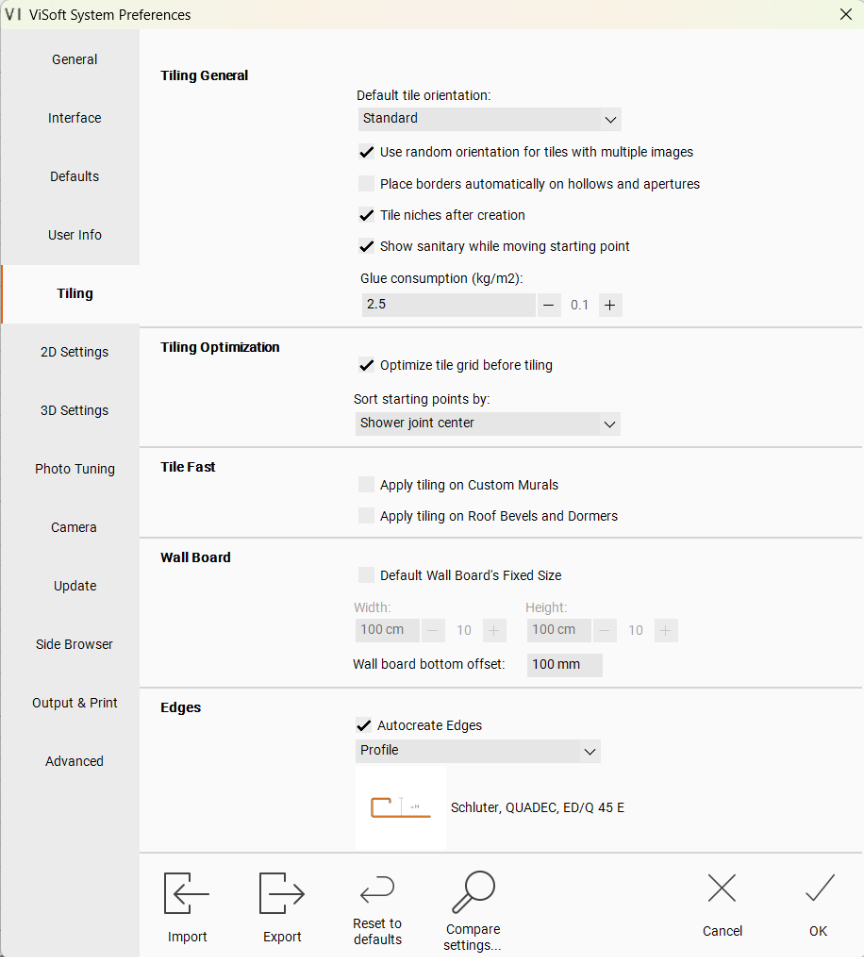
Tiling controls default tile orientation, placement behavior, optimization, Tile Fast coverage, wall-board sizing, glue consumption, and automatic edge profiles.
Tiling General
- Default tile orientation – sets the starting orientation for tile placement.
- Use random orientation for tiles with multiple images – varies image orientation for tile products that provide multiple images.
- Place borders automatically on hollows and apertures – adds borders to openings when enabled.
- Tile niches after creation – applies tiling to newly created niches.
- Show sanitary while moving starting point – keeps sanitary objects visible while a tiling starting point is moved.
- Glue consumption (kg/m2) – sets the glue quantity used for material calculations.
Optimization Tile Fast Wall Board and Edges
- Optimize tile grid before tiling – optimizes the grid before ViSoft calculates the layout.
- Sort starting points by – sets how candidate starting points are ordered.
- Apply tiling on Custom Murals – includes custom murals in Tile Fast when enabled.
- Apply tiling on Roof Bevels and Dormers – includes those roof surfaces in Tile Fast.
- Default Wall Board’s Fixed Size – enables fixed Width and Height for wall boards; Wall board bottom offset remains separately configurable.
- Autocreate Edges – automatically creates the selected edge Profile.
Figure 9 Tiling
2D Settings
UI path File > Preferences > 2D Settings
2D Settings controls drawing quality and optional guide lines shown in 2D planning views.
- 2D visualization quality – selects the rendering quality for 2D views.
- Draw human height projection line in 2D views – shows a horizontal reference line at the configured Height.
- Draw line for depth of the roof bevel at height 2m in Floor view – adds a Floor-view guide for the roof bevel depth at 2 m.
Figure 10 2D Settings

3D Settings
UI path File > Preferences > 3D Settings
3D Settings balances visual quality and navigation performance and controls sky, grids, tile depth, edge profiles, and Open VR room rotation.
- Visualization effects – selects the visual-effects preset.
- Image Quality – selects the 3D image-quality preset.
- Disable visualization effects during camera navigation – temporarily reduces effects while the camera moves.
- Default Sky Style – selects the sky used by default in 3D.
- Show land grid in 3D – shows the ground grid in the 3D view.
- Show three-dimensional tiles in 3D – displays tile thickness or relief as 3D geometry where supported.
- Show borders using 3D profile shape – uses the selected profile geometry for borders in 3D.
- Room rotation angle – sets the Open VR room-rotation step.
Figure 11 3D Settings
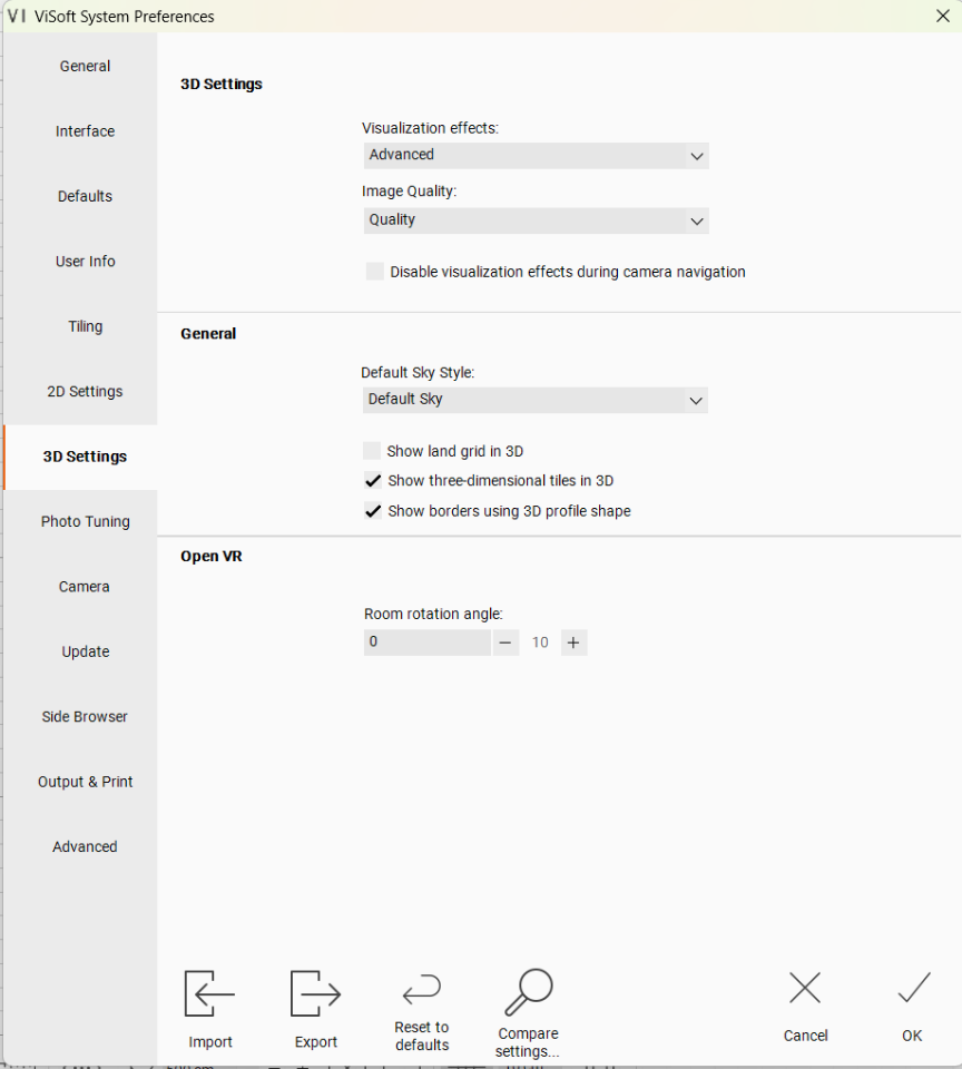
Photo Tuning
UI path File > Preferences > Photo Tuning
Photo Tuning configures the V-Ray rendering workflow, automatic image correction, image effects, fast-preview resolution, render-server behavior, cluster rendering, and the default picture watermark.
- Use V-Ray frame buffer for rendering – uses the V-Ray frame buffer for rendered output.
- Render engine – opens the render-engine configuration.
- Denoiser – reduces render noise; AI denoiser is a dependent option when supported and enabled.
- Auto-Exposure – automatically adjusts exposure; Auto-exposure compensation offsets the automatic result.
- Auto-White Balance – automatically corrects color balance.
- Shadow Detail Enhancement – increases visible detail in darker areas when enabled.
- Glare effect – adds glare to bright image areas.
- Chamfer Effect – softens sharp geometry edges in the render; Chamfer Effect Size (mm) controls the effect size.
- GI Saturation – controls saturation contribution in global illumination.
- Photo Tuning Fast resolution – sets the output size used by Photo Tuning Fast.
- Start Render Server with Windows – starts the render-server component with Windows.
- Use Photo Tuning cluster rendering – enables distributed cluster rendering; Cluster Rendering becomes available when the option and required environment are active.
- Use default watermark for picture – applies a default watermark; Add Watermark… configures it when the option is enabled.
Figure 12 Photo Tuning

Camera
UI path File > Preferences > Camera
Camera defines the initial perspective and viewpoint geometry, which automatic perspectives are added to favorites or the Navigation Panel, and how perspective animation behaves.
General
- Default Perspective – selects the perspective used as the default camera view.
- Default view height for Center Viewpoint – sets the center-view camera height.
- Default camera angle of view – sets the camera field-of-view angle.
- Automatically add these perspectives to favorites – selects named viewpoints such as From the door, washbasin, bath, shower, WC, flush, bidet, and Top.
- Up and down arrows – change the order of the selected automatic perspective entries.
- Add checked perspectives to Navigation Panel – adds the checked items to the Navigation Panel.
- Fit perspectives to maximum view – frames automatically generated perspectives to the maximum view.
Animation
- Animation list of perspectives – uses the perspective list as an animation sequence.
- Animate Camera while switching between Perspectives – moves the camera between viewpoints instead of switching immediately.
- Hide Walls during animation – hides walls during the animated transition.
- Use random order of perspectives for animation – randomizes the sequence.
- Animation Speed – sets the transition speed from Slow to Fast.
Figure 13 Camera

Update
UI path File > Preferences > Update
Update controls how ViSoft database updates are installed, optional scheduling, Fast update mode, proxy use, and centralized updates through ViSoft Server.
Internet Update settings
- Update mode – selects manual or automatic database update behavior.
- Install new updates – sets the automatic schedule and time when the selected mode enables scheduling.
- Fast update mode – performs a quick data update without downloading all data; necessary data is downloaded on demand.
- Use Proxy Server for Internet Connection – routes the update connection through a configured proxy.
ViSoft Server settings
- Enable ViSoft Server – uses ViSoft Server in a corporate network to update ViSoft programs automatically.
Figure 14 Update

Figure 15 Update alternate capture

Side Browser
UI path File > Preferences > Side Browser
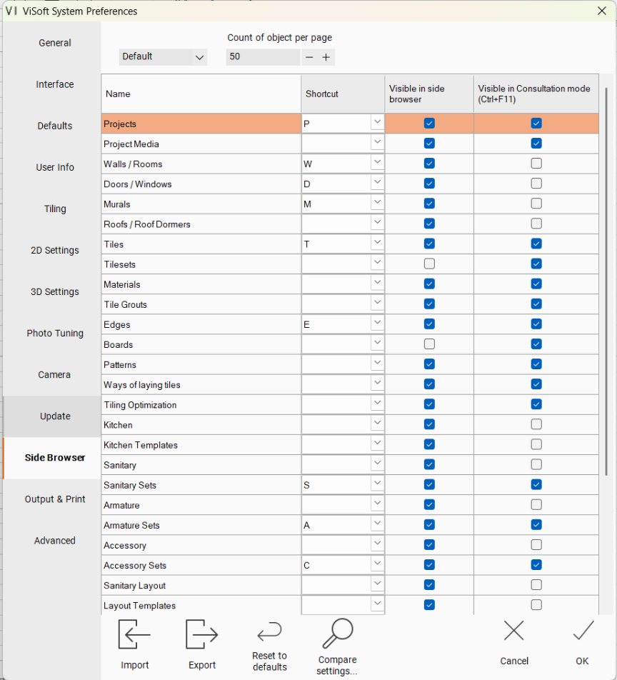
Side Browser defines the category configuration, keyboard shortcuts, visibility in the Side Browser, visibility in Consultation mode, and how many objects appear on a page.
- Configuration list – selects a saved browser configuration, such as Default.
- Count of object per page – sets how many objects are shown on one browser page.
- Name – identifies the browser category.
- Shortcut – assigns a keyboard shortcut to the category where supported.
- Visible in side browser – shows or hides the category in the standard Side Browser.
- Visible in Consultation mode (Ctrl+F11) – shows or hides the category in Consultation mode.
The table covers planning and catalog areas such as Projects, Project Media, Walls / Rooms, Doors / Windows, Murals, Roofs / Roof Dormers, Tiles, Tilesets, Materials, Tile Grouts, Edges, Boards, Patterns, tiling tools, Kitchen, Sanitary, Armature, Accessory, sets, and templates. Scroll to reach additional rows.
Figure 16 Side Browser
Output and Print
UI path File > Preferences > Output & Print
Output & Print provides two editors: Print Settings for printer and paper configuration, and Output Settings for the visual and content rules used by generated plans, lists, and picture printouts.
- Print Settings > Edit… – opens printer, PDF printer, Page Setup, and automatic page-orientation settings.
- Output Settings > Edit… – opens the detailed Output Settings window.
- Output configurations location – sets the folder used to store output configuration files.
- Save output configuration with project – stores the selected output configuration together with the project.
Figure 17 Output and Print

Print Settings
UI path File > Preferences > Output & Print > Print Settings > Edit…
Print Settings separates the standard printer from the PDF printer and provides page-level setup.
- Printer Setup – selects and configures the Windows printer used for printed output.
- PDF Printer Setup… – selects and configures the printer used for PDF output.
- Printer summary – shows the selected device, orientation, and paper size.
- Page Setup… – opens Paper Size, Orientation, and margin settings.
- Page autoorientation – allows ViSoft to choose page orientation automatically for the output.
Figure 18 Print Settings

Output Settings
UI path File > Preferences > Output & Print > Output Settings > Edit…
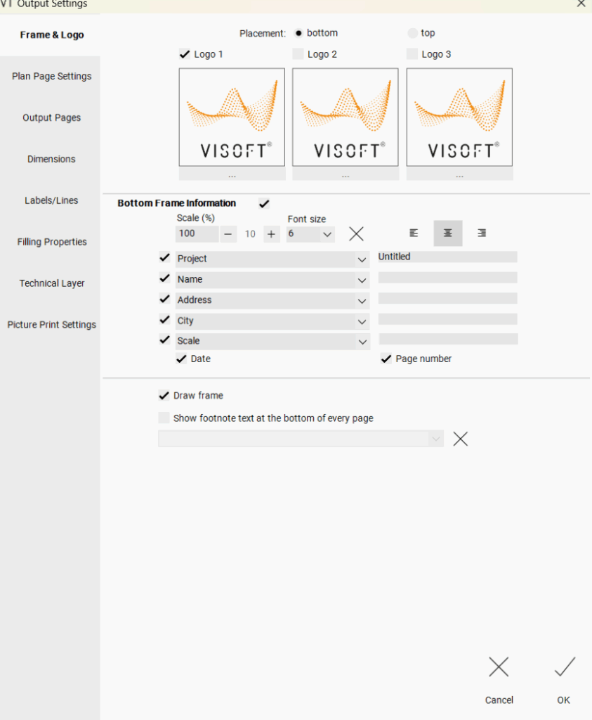
Output Settings contains seven pages: Frame & Logo, Plan Page Settings, Output Pages, Dimensions, Labels/Lines, Filling Properties, Technical Layer, and Picture Print Settings.
Frame and Logo
- Placement – places the frame information at the bottom or top.
- Logo 1 Logo 2 Logo 3 – enables up to three logo positions; the ellipsis button selects the image for each position.
- Bottom Frame Information – enables the frame information block in the captured bottom-placement configuration.
- Scale (%) and Font size – set the size of the frame content.
- Alignment controls – align the frame information text left, center, or right.
- Information rows – enable Project, Name, Address, City, Scale, Date, and Page number, with a source field or fixed value where available.
- Draw frame – draws the output page frame.
- Show footnote text at the bottom of every page – adds the selected footnote text to each page.
Figure 19 Output Settings Frame and Logo
Plan Page Settings
- Scale – selects Fit to page (standard scale) or another available scale mode.
- Standard scales – lists available scales; Add and Delete maintain the list.
- Plan aligning – uses a nine-point selector to position the plan on the page.
- Inner margins – sets Left, Right, Top, and Bottom spacing inside the output page.
- Page autoorientation – applies automatic orientation to the plan page.
- Page Setup… – opens the printer-driver Page Setup dialog.
Figure 20 Output Settings Plan Page Settings

Figure 21 Page Setup

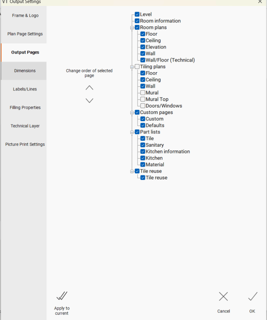
Output Pages
Use the tree to include or exclude complete output groups or individual pages. The captured groups include Level, Room information, Room plans, Tiling plans, Custom pages, Part lists, and Tile reuse. Child pages include Floor, Ceiling, Elevation, Wall, Wall/Floor (Technical), Mural, Mural Top, Doors/Windows, Custom, Defaults, Tile, Sanitary, Kitchen information, Kitchen, Material, and Tile reuse.
- Change order of selected page – moves the selected output page up or down.
- Apply to current – applies the selected Output Pages configuration to the current project or output context.
Figure 22 Output Settings Output Pages
Dimensions
- Dimension Properties – sets Font, Size, Color, and Thickness; Apply to all copies the properties across applicable pages.
- Extension Lines Properties – sets Style, Thickness, and Color, with Apply to all.
- Color dimensions by category – assigns different colors to Wall, Door / Window / Hollow, Mural, Group, Sanitary, Armature, Furniture, Heating, Electrical, Water connection, Others, and cabinet categories.
- Dimension Apex Mode – selects one of the displayed endpoint styles.
- Show extension lines – shows dimension extension lines.
- Show Door / Window / Hollow height on a floor plan – adds opening heights to the Floor plan.
- Show dimensions for objects on floor page which are closer than – sets the proximity threshold for Floor-page object dimensions.
- Minimum mural size to draw dimensions – sets the minimum mural dimension threshold.
- Type – selects Full or From one side. With an option to start from the left or from the right.
- Auto Dimensioning… – opens the category and view matrix for automatic dimensions.
Figure 23 Output Settings Dimensions

Automatic Dimensioning
The Automatic Dimensioning matrix controls which product categories and subcategories receive dimensions and where those dimensions appear. Rows can use a Dimension Type such as To sides or To center. Separate columns control Ceiling, Floor, Wall (Horizontal), Wall (Vertical), Technical Floor, and Technical Wall output. Description and Type help distinguish detailed database entries. Expand category rows to reach subcategories and individual types.
- Check Selected – enables the selected rows or cells.
- Uncheck Selected – disables the selected rows or cells.
- Default – restores the automatic-dimensioning defaults for this dialog.
- OK and Cancel – accept or discard the matrix changes.
Figure 24 Automatic Dimensioning

Labels and Lines
- Symbol Properties – sets the general symbol Color and a separate Electrical symbols color.
- Line Properties – sets Thickness and Color and enables a start arrow and/or end arrow.
- Label Properties – sets Font, Size, Text color, Background color, Hatch, and Frame color.
- Index Properties – sets Font, Size, and Text color for index labels.
- Apply to all – copies the settings in its property group to all applicable output pages.
- X controls – clear an optional background, hatch, frame, or text-color override where shown.
Figure 25 Output Settings Labels and Lines

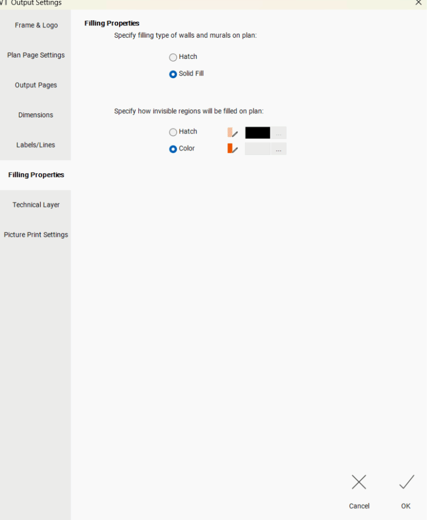
Filling Properties
- Specify filling type of walls and murals on plan – selects Hatch or Solid Fill.
- Specify how invisible regions will be filled on plan – selects Hatch or Color and configures the selected appearance.
Figure 26 Output Settings Filling Properties
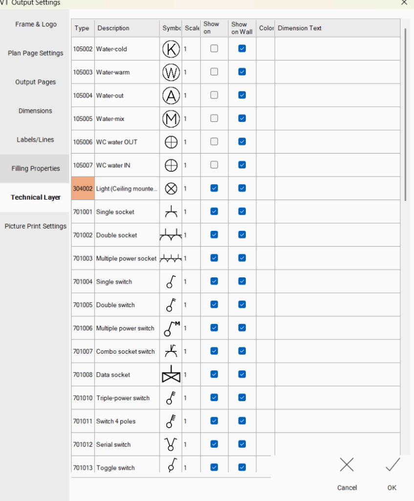
Technical Layer
Technical Layer maps installation types to drawing symbols. Each row can contain Type, Description, Symbol, Scale, visibility on the plan, visibility on Wall output, Color, and Dimension Text. The captured rows include cold, warm, outlet, and mixed water points, WC water connections, lights, sockets, and switches. Scroll to reach the full catalog.
Figure 27 Output Settings Technical Layer
Picture Print Settings
- Fit picture to frame – scales the picture to the frame dimensions.
- Fit to max – uses the maximum available size while preserving the picture within the print area.
Figure 28 Output Settings Picture Print Settings

Advanced
UI path File > Preferences > Advanced
Advanced contains database and custom-data path configuration plus an option to include GAEB data in a project archive.
- Advanced path configuration – opens the editor for projects, databases, libraries, templates, output labels, recovery data, and other shared locations.
- Add GAEB file to project archive – includes the GAEB file when ViSoft creates a project archive.
Figure 29 Advanced

Advanced Path Configuration
- Projects location – default project storage.
- Object databases location – object database root.
- Tile database location – tile database file.
- Material library location – material library root.
- Custom mural location – custom mural data.
- Tile boards location – tile-board definitions.
- Tile patterns location – tile-pattern definitions.
- Tile textures location – tile texture files.
- Auto recovery projects location – Auto-Recovery storage.
- Output labels location – labels and symbols used by output.
- Phototuning ScheduledTasks location – scheduled Photo Tuning tasks.
- Layout Templates – sanitary layout templates.
- Basket root location – root folder for basket data.
Environment rule The C:\ProgramData paths in the supplied screenshot are examples from one computer. A network installation or customized deployment can use different locations.
Figure 30 Advanced Path Configuration

